IR/INFO Conference
Proceedings 2018
List of articles contained in the IR/INFO 2018 Proceedings:
John (Jack) Allinson, II AMS®
Level III Certified Infrared Thermographer
Allinson Infrared Inspection Services, Inc.
222 University Blvd. North #2 Jacksonville, FL 32211
Ph: 904-721-2177
Charles Hazouri, CMS
Level III Certified Infrared Thermographer
Offshore Marine Inspections 500 Mandeville Street, Unit 10 New Orleans, LA 70117
Ph: 504-450-8044
Applications of sUAV’s (Drones) for Marine Surveying
Abstract:
Jack is an Accredited Marine Surveyor (SAMS-AMS) and Charlie is a Certified Marine Surveyor (NAMS-CMS).
Both of them recognize the value of images both infrared and visual to document the conditions of the vessels and their systems.
While they both routinely use visual and infrared thermal imaging from a ground based vantage point, they recognize the importance of gaining an aerial prospective.
To this end they use videography from sUAV’s. Join Jack and Charlie as they review the equipment they use and show the results of various applications.
Oliver Beauchemin
Owner, Accolade Group

AB & MA Boston College
Cand PhD Brown University
SEO Certified: Search Engine Marketing
Professionals Organization
SEO Certified: Yoast Academy
Accolade Group of Vermont, LLC: Owner
Forest Gate Media, LLC: Partner
P O Box 10 Waterville, VT 05492
Ph: +1 802.238.8020
Ph: +91 812.660.4253
Step-by-Step to Increase Your Website Rank in Google
Abstract:
Once considered a novelty, the internet is now a part of everyday life. In order to compete in the 21st century, businesses must not only have a website; it must be visible within search engines such as Google. With hundreds of websites related to infrared inspection services, ensuring website visibility is becoming increasingly complex.
This presentation will provide website owners with crucial information regarding website design and maintenance while answering some of the most frequently asked questions including:
– How do I get on page 1 of Google?
– How do I get there fast?
– Can I do it myself?
Hunter Beebe
Level II Thermographer
Diamond Technical Surveys, LLC

23221 Aldine Westfield Road, Suite 710
Spring, Texas 77373
Ph: 281-379-6454
WYE Sections
Abstract:
Wye sections are found in many, various refining processes. They typically serve to deliver product to be mixed with air or catalyst into a reaction chamber. Reactions usually generate heat, sometimes in the neighborhood of 1300 degrees Fahrenheit or greater. Internal refractory linings are used to keep heat in the process, but due to abrasion via flow and pressure, the refractory lining can degrade over time.
Infrared thermography is a great tool to identify and monitor areas of refractory damage in Wye sections. Steps to mitigate heat transfer to the shell and recommendations of areas to inspect and repair the refractory lining during turnarounds are possible through the implementation and execution of an infrared inspection program.
This presentation will explain the design of a Wye section, its function in the refining process, and how infrared thermography can help avoid unplanned outages.
Philip M. Conte
Senior Test Engineer (retired)

PSEG Power
2756 Route 737
Kempton, PA 19529
Ph: 973-625-1708
Thermographic Inspection of Oil Cooled Transformers
Abstract:
When reporting thermal anomalies on exposed electrical components, data such as location, date, ambient conditions, temperature rise and load are usually recorded.
But, when inspecting oil cooled substation transformers there are other key pieces of information that should be included in the report.
This information will help system engineers diagnose the cause of the thermal anomaly, order specific parts and easily derive the action required to normalize cooling or conservatively de-rate the asset in terms of load carrying capability until the repair can be completed or a replacement can be installed.
This presentation will go over some common thermal anomalies to look for and data that should be recorded and where to find it when inspecting large oil cooled transformers.
It will also touch on how to automatically import nameplate data from a database into your report to save time and data space by avoiding redundant information.
John E. Davis
Level III Certified Infrared Thermographer
Energy Management Consultants
1660 Landfall Circle
Bartonville, TX 76226
Ph: 931-248-3729
Electrical Property Risk Management & Infrared Thermography
Abstract:
What is the difference between “Maintenance” infrared inspections and “Property” infrared inspections? A maintenance infrared inspection should be restricted to every day operations. The Maintenance Manager’s responsibility is defined as short term – to keep the production line up and operating. A property infrared inspection should be centered on the potential of catastrophic or major losses relating to electrical fires, business interruption and plant safety.
The Property Risk Manager’s responsibility is to use his/her best judgment to determine the amount of exposure for a fire, business interruption or personnel safety the company is willing to accept and it is defined as long term. Inspection criteria are centered on primary transformers, internal distribution substations, overhead distribution bus, air compressors, specialty process machines, and review of site contingency plans.
This presentation will cover NEC-70E and OSHA-1910 visible code violations combined with infrared thermal inspection findings for developing suggested repair recommendations. We will examine the site inspection results and equipment severity classifications for all observations listed, and place them in a table format for final review and recommendations.
Marie Getsug, PMP, CMRP, CRL
Level II Certified Infrared Thermographer
Jacobs Engineering Group, Inc.

Clarksville, MD 21029
How to Lead Design for Reliability (DfR) with Stage Gate Triggers
Abstract:
Asset Management has introduced a few key concepts which require a shift from focusing on initial investment to optimizing the life-cycle cost. The basis for such decisions are rooted in a risk-based and science-based approach to understanding the requirements of the asset throughout its useful life. The risk-based approach drives prioritization and optimization; whereas, the science-based approach honors the Subject Matter Experts (SME’s) experience as well as seeking meaningful data to drive decisions. Both must be applied in the concept and design phases to be effective.
Shifting the Project Management Office (PMO) and the Capital Engineering Process from a mindset of initial cost, scope and schedule to a focus on Total Cost of Ownership (TCO) and Life Cycle Cost (LCC) requires a catalyst for change. Design for Reliability (DfR) answers this requirement with a methodology that blends aspects of statistics, probability and reliability theory, and engineering analysis throughout a product lifecycle to evaluate, predict, and verify the application of robust design. Through application of DfR practices, the demand for highly-reliable systems can be met while ensuring that the latest methods for the assessment of robust design and risk-management are properly addressed. The design and concept stage gates become the most significant triggers for DfR and the mechanism for the timely application of each DfR element.
Experiences introducing and customizing a DfR Program and toolkit to achieve a Corporate Vision and optimize the performance of the assets throughout their useful life will be shared. Stakeholders with any level of responsibility for these assets are being called upon to contribute their experience in the concept and design phases, core to both Front End Planning (FEP) and DfR. A governance structure that supports, funds and allows for the input of these Stakeholders at these timely stage gates is fundamental to the success of a DfR Program.
Chad Herrick
Detec Systems, LLC

PO Box 31725
Bellingham, WA 98228
Ph: 970-759-6312
Electronic Leak Detection Testing Methods
Abstract:
Electronic Leak Detection (ELD) methods are used for determining discontinuities in the form of breaches and seam voids in low slope roofing and waterproofing assemblies.
The first ELD method was developed in Germany in the 1970’s. Since then, several different advancements have been made to the original EFVM methods allowing for greater accuracy and speed of testing.
ELD methods can be used on new construction to locate and repair breaches before they cause extensive water saturation in the roofing assembly. ELD methods can also be used in forensic testing situations to locate where water is entering the roofing/waterproofing assembly.
When ELD methods are used in conjunction with thermal imaging, both the extent of water inundation along with the locations of the membrane breaches can be determined.
Ben Hixson
United Infrared, LLC / Hixson Consultants, Inc.

947 First Avenue West Alabaster, AL 35007
Ph: 205-663-2220
Inspecting Modern Roofing System Assemblies – What Thermographers Must Know
Abstract:
Since the 1980’s thermal imaging has proven a useful tool for detecting latent moisture within low-slope roofing systems. Advancements in technology and materials over the past 40 years have resulted in commercial roofing systems that bear little resemblance to those of the mid twentieth century.
Although thermal imaging remains a viable tool for detecting moisture within modern roofing systems, today’s roofing systems present challenges that, if not properly addressed, can compromise the accuracy of inspection results.
This presentation will cover both historical and present day roofing system membranes, cover boards, insulation types, substrates and decks along with what thermographers need to know in order to obtain optimal results from many types of roofing assemblies.
Sonny James
Managing Director
Thermal Diagnostics Limited

15 Robertson Street, Les Efforts East
San Fernando, Trinidad & Tobago, West Indies
Ph: 868-653-9343 / 868-657-6572
The Dangers of Improper Thermal Imager Settings During Thermographic Inspections
Abstract:
Over the years, I have viewed so many images and reports of thermographic inspections being carried out with improper imager settings, that I have ended up adding a section in my training courses on “How Not To Do An IR Survey”. I show upcoming as well as experienced thermographers actual real world examples of poor and careless IR work.
This paper will show how improper thermal imager settings can result in potentially dangerous outcomes with plant equipment, personnel safety, and property. Examples of shoddy insulation, electrical, and motor inspections using improper thermal imager settings will also be shown.
This paper will further discuss the importance of possessing adequate knowledge and experience for the application and equipment being inspected to effectively detect discontinuities. It will also briefly highlight the recent changes to ASNT SNT-TC-1A Thermal Infrared certification, which now addresses this important issue.
Josh Kneifel
President / Co-Owner
BirdsiVideo

PO Box 1014
Carmel, IN 46082
Ph: 317-383-7312
Gordon Dowrey
Principal
BirdsiVideo

PO Box 1014
Carmel, IN 46082
Ph: 317-383-7312
Large Area Asset Thermal Inspections with UAV Technology
Abstract:
For over 30 years, thermal imaging has been used from manned aircraft for a wide variety of applications. Presently, the world is experiencing another technology disruption that is as deep and encompassing as the 1980’s IT revolution. Unmanned Aerial Vehicles (UAVs), also known as drones, are reshaping industries ranging from insurance to agriculture. Learn how your professional thermography business can be transformed by adopting the use of UAVs.
Ed Kochanek
Director of Sales,
Key Account Manager

FLIR Systems, Inc.
22 Overlook Drive
Woolwich, NJ 08085
Ph: 866-379-4022
Mobile: 609-932-8795
Drones: The New Frontier of Thermal Imaging
Abstract:
For over 30 years airborne thermal imaging systems have provided a unique perspective for a number of applications. In the past, thermal imaging systems were expensive and were limited to use with either helicopters or fixed-wing aircraft. The recent introduction of affordable, unmanned aerial vehicles (UAVs), also known as drones, combined with lightweight thermal imagers has made aerial thermal imaging more affordable than ever.
This paper and presentation will discuss the many uses of thermal imaging from the air.We will discuss search and rescue, utility and building applications and how far away you can be to see someone or something. We will also discuss the latest trends and what to look for in a thermal imager when you are above your target.
Alan Kowalik
Level III Certified Infrared Thermographer

Central Texas Thermal Imaging
1925 Plantation Drive
Round Rock, TX 78681
Ph: 512-468-0841
The Future of Thermal Imaging in Bridge Deck Inspection
Abstract:
With tightening maintenance and replacement budgets and an increasing number of bridges being added to their inventories, states, cities, counties and other bridge owners are looking for ways to stretch not only the life of their assets but also their budgets.
Traditional methods of determining bridge deck delaminations are costly and time consuming not only to the bridge owners but also the traveling public. These methods also put inspectors at risk for injury and increase the chances of automobile accidents. New technologies using infrared thermal imaging offer the owners information about bridge deck conditions at a cost savings and at a fraction of the time it used to take to collect the data.
This presentation will present an overview of traditional methods and how new methods will not only save time, but will also give the bridge owners information they need to make decisions on how to spend monies for individual projects or for the long-term maintenance of structures. We will also touch on the use of infrared in other transportation projects.
Alan Kowalik
NEXCO-West USA

8300 Boone Blvd, Suite 240
Vienna, VA 22182
Ph: 703-734-0281
Structural Concrete Inspection by Infrared Thermography
Abstract:
The USA is experiencing an oncoming wave of structures becoming obsolete and in need of repair or replacement. The average age of the country’s bridges is about 43 years and a significant portion of these bridges are considered structurally deficient. Using the FHWA’s Structure Inventory and Appraisal (SI&A) database, bridge inspectors determine condition ratings of bridge components. These ratings, however, are generally subjective and are dependent on individual inspector knowledge and experience, along with varying field conditions. Preemptive steps must be taken to effectively prioritize maintenance of deficient structures.
In order to enable the efficient collection of initial diagnostic data and facilitate anticipatory decision-making by pinpointing deficient areas in concrete surfaces, NEXCO-West USA has developed a methodology for scanning structural surfaces using infrared thermography. The method uses software which highlights deficient areas in a variety of applications, including 1) mobile highway inspections, 2) marine inspections, and 3) stationary inspections from short to long distances in respect to the target surface.
In this presentation, we present data from multiple locations, and examine the efficacy of the software’s detection functionality. By using this method, we aim to minimize man-hours in the field and to give bridge inspectors the tools to gain more accurate data in initial inspection phases, which can be used to objectively rate structural conditions.
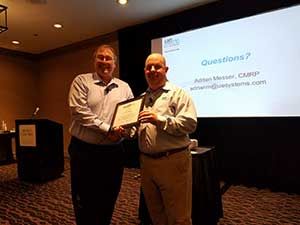
Adrian Messer
Manager of US Operations

UE Systems, Inc.
Ph: 864-224-4517
Cell: 914-282-3504
Planning & Performing an Effective Ultrasonic Compressed Air & Gas Leak Survey
Abstract:
Contrary to what some might think, compressed air is not free. In fact, because of what it takes to produce it compared to what is generated, it is often considered the most expensive utility in a typical manufacturing facility. To further add to the problem, the US Department of Energy notes that more than 50% of all compressed air systems have energy efficiency problems. Air Compressor experts have also estimated that as much as 30% of the compressed air generated is lost via leaks in the compressed air system.
Compressed air and gas leak detection with ultrasound remains the most widely used application for this technology. By locating compressed air/gas leaks with ultrasound and then making the necessary repairs, ultrasound technology is a great application that can have tremendous payback in the dollars lost due to compressed air and compressed gas leaks. Recent advancements in compressed air leak detection and reporting allow for the quantification of the dollars lost and the CFM loss from compressed air leaks.
This presentation will discuss the use of ultrasound technology for planning and performing an effective ultrasonic compressed air leak survey that focuses on the evaluation, detection, identification, tracking, repair, verification, and reevaluation processes centered around a compressed air leak detection program. By implementing these steps, a typical manufacturing plant could reduce its energy waste by roughly 10 to 20 percent.
Arturo Nunez
Substation Reliability COE Manager

Mistras Group, Inc.
195 Clarksville Road
Princeton Junction, NJ 08550
Ph: 609-716-4162
Condition Assessment of HV Equipment – Multiple Techniques Approach
Abstract:
Power transformers are common features found in many commercial and industrial facilities.
In order to ensure reliability and long service life, transformers must be regularly tested and maintained.
Evaluating test results obtained with multiple test techniques provides an accurate assessment of power equipment allowing maintenance personnel to decide the next steps to ensure equipment reliability.
This paper discusses the application of multiple in-service test techniques for power transformers along with case studies showing how internal inspections correlate to test data collected prior to shutdown.
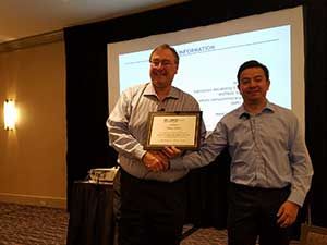
Tim Rohrer
CMRP Founder & President

Exiscan Electrical Safety Products
1645 Lyell Avenue
Rochester, NY 14606
Ph: 585-366-0333
Infrared Windows: Seven Keys to Effective Use & Installation
Abstract:
Infrared (IR) inspection windows are fast becoming a standard method of conducting periodic infrared inspections of energized electrical equipment. The popularity of IR windows has boomed in recent years due in large part to a convergence of safety standards (such as NFPA 70E and CSA Z462), electrical preventive / predictive maintenance standards (such as NFPA 70B and CSA Z463), and the trend of equipment designed to restrict access to energized components.
But how can you get the most out of your IR inspections when using IR windows? This presentation provides 7 key tips to keep in mind when using or installing IR windows: Transmission rate compensation, transmission degradation, field-of-view, obstructions, emissivity, documenting the layout of the enclosure, and other inspections to consider.
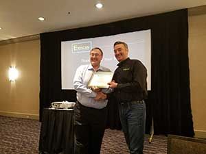
Joseph C.K. Sayer
Aerial Inspection & Filming Services

2232 South Main Street, Suite 392
Ann Arbor, MI 48103
Ph: 844-90-DRONE (844-903-7663)
Drones 101
Abstract:
For those who want to operate a UAS (Unmanned Aerial System), aka Drones, in the National Airspace System, there are many issues that are critical to understand.
We have all heard about the industry-specific value this emerging technology can present to entrepreneurs, but a clear understanding of the FAA regulations, NTSB rules and how to safely integrate all this into a very complex environment is a must.
This presentation will explore the regulatory side of this exciting new business opportunity, and how to capitalize on the financial benefits that this technology can provide thermographs.
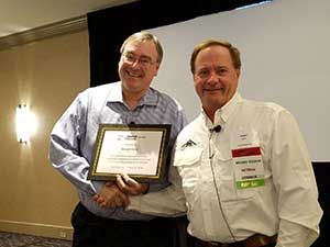
Gregory R. Stockton
President, Stockton Infrared

8472 Adams Farm Road
Randleman, NC 27317
Ph: 800-248-SCAN (7226)
Thermal Infrared Surveying of Photovoltaic Solar Fields – Utility-Scale, Commercial Ground-Mount and Roof-Top
Abstract:
Thermal infrared surveys of new solar fields are a great way to commission solar installations in-situ. After analyzing and commissioning over two gigawatts of solar panels in the past five years, we have figured out what works and more importantly, what does not work.
All solar fields are not created equal. Before planning a site visit, the thermographer must take into account the size and layout of the field, the types of panels, how the panels are wired, and then the best timing of the survey. First, the platform and methodology for scanning needs to be chosen, then scheduling can take place. Correct timing of the survey is the most important factor because the amount of solar insolation is absolutely critical to successful testing. To accomplish the testing under good conditions, many factors need to be predicted with accuracy; these include ambient conditions such as rain, sun, clouds, wind speed and direction during the survey and preceding the survey.
This presentation will discuss the above items as well as the vantage points from which a thermographer can survey a solar installation and the advantages and disadvantages of each.
Wayne Swirnow
President
Level III Certified Infrared Thermographer

Infrared Imaging Services, LLC
PO Box 221
New City, NY 10956
Ph: 845-641-5482
www.InfraredImagingServices.com
IRman@infraredimagingservices.com
Electrical Infrared Inspection – Why Components Get Hot and an Application Story of Hot 50A Oven Receptacles
Abstract:
Thermography is an important diagnostic tool used to locate defects in the conductive path of electrical equipment. Because every component contains some inherent resistance which causes heat to be generated as a current pass through it, we can use a thermal imager to “see” these components in action. Viewing this heat allows the understanding of the flow of power through the system, gives us the ability to imagine its resistance and understand where there may be defects in the current’s path.
Most electrical gear we encounter during the course of an infrared inspection such as wires, switches, connectors, fuse clips, and circuit breakers, are engineered to avoid getting excessively warm when operated below its maximum current rating. Some devices such as heaters, relays, and contactor coils are designed to be warm, and even “hot” when running normally. For most equipment, the heat that is generated is a product of the current flowing through it and the equipment’s resistance.
As the current flow increases and the resistance stays fixed, the additional heat will be seen uniformly across the components. Conversely, a localized defect in the conductive path of the equipment usually causes a localized increase in resistance, which in turn will cause additional heat to be generated at that isolated location.
This presentation will use Ohm’s law as the vehicle to illustrate why electrical current flow causes components to get warm, and why a local increase in resistance causes the excessive heat typically referred to as a “hot spot”. Using Ohm as a foundation, this presentation will discuss a real-life situation of 50 amp oven plug receptacles, which were found to be overheating during an inspection of the wiring in an apartment building.
Tony Yin
General Manager
FOTRIC Precision Instruments
2021 Nottingham Place
Allen, TX 75013
Ph: 214-235-4544
Data-Driven Intelligent PdmIR System – The Future of IR Service
Abstract:
With the increased quantity of infrared thermal images, accumulated historical data, and complex diagnosis criteria, it becomes more and more challenging for IR service professionals to effectively manage, organize, locate and analyze the thermal data, and generate high-quality data statistics and reports for the customers.
This presentation will introduce an innovative data-driven intelligent PdmIR system, its solutions to the challenges, and how it can help IR professionals to do the inspection job intelligently, save significant time to create reports, bring more value to customers, and generate more business.
Austin P. Tucker
AVP, PI Risk Services, Global Risk Solutions
QBE North America
Arlington, TX
Ph: 469-233-9606
Inevitability and Insurance at a Pivot Point
Abstract:
Insurance, particularly property and casualty, has been slow to adapt to the digitalization of the worldwide economy. For too long, insurance has resisted change, relying on a model that hasn’t had a significant change since 1686 when Lloyd’s of London was founded. Since then, insurance has predominately stuck with the same model of doing business the same way and letting the world change around it.
With the rise of insuretech companies, a more educated consumer market, and a general shift in willingness to accept the status quo, insurance has begun to realize it is in need of change or it will be drastically changed or, maybe, replaced altogether.
This presentation will discuss the current state of the insurance industry and what must be done in order for it to adapt and succeed in the future.
Who Should Attend
- Thermographers
- Process Control Supervisors
- Maintenance Managers
- Loss Control Specialists
- Reliability Engineers
- P/PM and NDT Personnel
- Manufacturers
- Quality Assurance Inspectors
- Home and Building Inspectors
HOW YOU WILL BENEFIT
- Education
- Learn New Technology
- Networking
- See Latest Developments
- Share Ideas
- Discover New Applications & Techniques


